Cell Emulator card
Description of the Cell Emulator card for HIL Connect hardware
Note: For more information on how to configure your card in
Typhoon HIL Control Center, please refer to the
Cell Emulator Card parametrization
documentation.
The BMS Cell Emulator card is designed to provide battery cell emulation capabilities. It includes a controlled voltage output (operated by a HIL AO) and a current measurement input (linked to a HIL AI). Additionally, the card is equipped with fault insertion features (controlled via HIL DO) and can simulate reverse polarity.
Cell Emulator card revisions
| Code | Revision | Part number |
|---|---|---|
| LN | 3.2 | 24252 |
Cell Emulator card hardware specification
| Parameter | Value |
|---|---|
| Type | Cell emulator |
| Number of channels | 4 |
| Input signal range | ±10 V |
| Output signal range | ±5 V, ±1 A |
| Isolation | 60 V channel-to-channel 400 V channel-to-earth |
| Bandwidth (-3dB) | DC to 20 kHz |
| Fault emulation | Open circuit Short circuit Reverse polarity |
Cell Emulator card hardware settings
| Option | Method | Possible options |
|---|---|---|
| Drive channel selection, in groups of 4 | Via internal DIP switches | Card driven from: HIL AO1..4, or HIL AO5..8, or HIL AO9..12, or HIL AO13..16 |
Cell Emulator card connector data
| Parameter | Value |
|---|---|
| Connector outline | 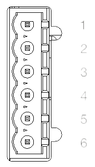 |
| PCB connector part number | 1923908 |
| Mating connector part number | 1942413 |
Cell Emulator card pinouts
Note: The following pinouts assume that the card is configured for AO1..AO4 option. If another
setting is applied, loaded HIL channels also change, e.g. AO5..AO8.
| Connector | Pin | Signal | Related HIL channel |
|---|---|---|---|
| X1 | 1 | OUT+_1 | AI1 + AO1 |
| X1 | 2 | OUT_BMS_1 | AI1 + AO1 + DO1 |
| X1 | 3 | SENSE+_1 | AI1 + AO1 |
| X1 | 4 | SENSE-_1 | AI1 + AO1 |
| X1 | 5 | OUT-_1 | AI1 + AO1 |
| X1 | 6 | OUT-_1 | AI1 + AO1 |
| Connector | Pin | Signal | Related HIL channel |
|---|---|---|---|
| X2 | 1 | OUT+_2 | AI2 + AO2 |
| X2 | 2 | OUT_BMS_2 | AI2 + AO2 + DO2 |
| X2 | 3 | SENSE+_2 | AI2 + AO2 |
| X2 | 4 | SENSE-_2 | AI2 + AO2 |
| X2 | 5 | OUT-_2 | AI2 + AO2 |
| X2 | 6 | OUT-_2 | AI2 + AO2 |
| Connector | Pin | Signal | Related HIL channel |
|---|---|---|---|
| X3 | 1 | OUT+_3 | AI3 + AO3 |
| X3 | 2 | OUT_BMS_3 | AI3 + AO3 + DO3 |
| X3 | 3 | SENSE+_3 | AI3 + AO3 |
| X3 | 4 | SENSE-_3 | AI3 + AO3 |
| X3 | 5 | OUT-_3 | AI3 + AO3 |
| X3 | 6 | OUT-_3 | AI3 + AO3 |
| Connector | Pin | Signal | Related HIL channel |
|---|---|---|---|
| X4 | 1 | OUT+_4 | AI4 + AO4 |
| X4 | 2 | OUT_BMS_4 | AI4 + AO4 + DO4 |
| X4 | 3 | SENSE+_4 | AI4 + AO4 |
| X4 | 4 | SENSE-_4 | AI4 + AO4 |
| X4 | 5 | OUT-_4 | AI4 + AO4 |
| X4 | 6 | OUT-_4 | AI4 + AO4 |