Description of the Analog Input card for HIL Connect hardware
The Analog Input card offers 16 analog inputs linked to 16
HIL AI channels. Each input can be configured for voltage or current mode
(supported in revisions 2.5 and later).
Analog Input card revisions
Table 1. Card revisions
| Code |
Revision |
Part number |
| KQ |
2.6 |
26304 |
| LV |
2.5 |
24572 |
| KQ |
2.4 |
23955 |
Analog Input card hardware specification
Table 2. Hardware Specification
| Parameter |
Value |
| Type |
Analog input |
| Number of channels |
16 |
| Input signal range |
±10 V or ±40 mA |
| Output signal range |
±10 V |
| Input Resistance |
10 Ω |
| Bandwidth (-3dB) |
DC to 100kHz |
| Accuracy |
0.5% + 50 uA |
| Isolation |
No |
Analog Input card hardware settings
Table 3. Hardware Options
| Option |
Method |
Possible options |
| Voltage or current mode
selection |
Via internal DIP switches |
Each channel can be set to voltage or current
mode |
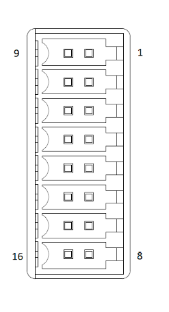
Analog Input card connector data
Table 4. Connector data
| Parameter |
Value |
| Connector outline |
 |
| PCB connector part number |
1289320000 |
| Mating connector part number |
1277530000 |
Analog Input card pinouts
Note: The following pinouts assume that all channels are set to ±10 V input voltage. If
another setting is applied, signal ratings also change, e.g. ±40 mA.
Table 5. Pinout - X1
| Connector |
Pin |
Rating |
Related HIL channel |
| X1 |
1 |
±10 V |
AI1 |
| X1 |
2 |
±10 V |
AI2 |
| X1 |
3 |
±10 V |
AI3 |
| X1 |
4 |
±10 V |
AI4 |
| X1 |
5 |
±10 V |
AI5 |
| X1 |
6 |
±10 V |
AI6 |
| X1 |
7 |
±10 V |
AI7 |
| X1 |
8 |
±10 V |
AI8 |
| X1 |
9..16 |
GND |
HIL GND |
Table 6. Pinout - X2
| Connector |
Pin |
Rating |
Related HIL channel |
| X2 |
1 |
±10 V |
AI9 |
| X2 |
2 |
±10 V |
AI10 |
| X2 |
3 |
±10 V |
AI11 |
| X2 |
4 |
±10 V |
AI12 |
| X2 |
5 |
±10 V |
AI13 |
| X2 |
6 |
±10 V |
AI14 |
| X2 |
7 |
±10 V |
AI15 |
| X2 |
8 |
±10 V |
AI16 |
| X2 |
9..16 |
GND |
HIL GND |