Description of the 24V Analog Output card for HIL Connect hardware
Figure 1. 24V Analog Output card HW
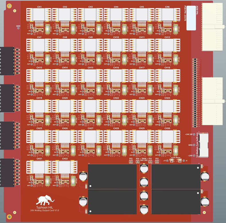
The 24V Analog Output card amplifies the analog signal voltage of HIL Simulator devices from ±10V to ±24V, by applying a gain factor of 2.4.
24V Analog Output card revisions
Table 1. Card revisions
| Code |
Revision |
Part number |
| MW |
1.0 |
25371 |
24V Analog Output card hardware specification
Table 2. Hardware Specification
| Parameter |
Value |
| Type |
Analog output |
| Number of channels |
32 |
| Input signal range |
±10 V |
| Output signal range |
±24 V |
| Gain |
2.4 |
| Max current per channel |
200 mA, limited to no more than 10 channels at the same time. |
| Nominal current per channel |
100 mA |
| Bandwith |
Max. 100 kHz |
| Max. capacitive load |
33 nF @ 100 kHz |
| Main Fuse |
5 A |
| Fuse per channel |
250 mA |
| Isolation |
No |
Simplified Schematic
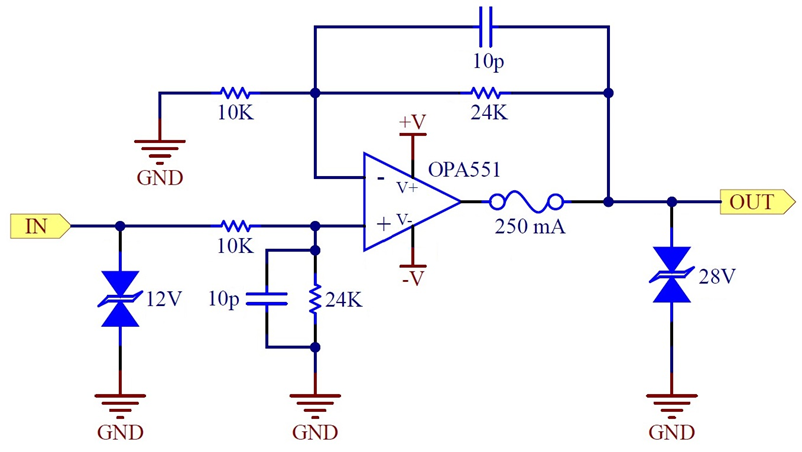
Figure 2 shows the simplified schematic of the gain applied to the Analog Outputs with the Analog Output card.
Figure 2. 24V Analog Output card schematic
BMS Analog Output card connector data
Table 3. Connector data
| Parameter |
Value |
| Connector outline |
 |
| PCB connector part number |
1289320000 |
| Mating connector part number |
1277530000 |
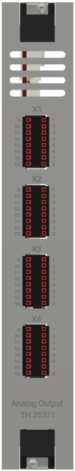
24V Analog Output card pinouts
Table 4. Pinout - X1
| Connector |
Pin |
Rating |
Related HIL channel |
| X1 |
1 |
±24 V |
AO1 |
| X1 |
2 |
±24 V |
AO2 |
| X1 |
3 |
±24 V |
AO3 |
| X1 |
4 |
±24 V |
AO4 |
| X1 |
5 |
±24 V |
AO5 |
| X1 |
6 |
±24 V |
AO6 |
| X1 |
7 |
±24 V |
AO7 |
| X1 |
8 |
±24 V |
AO8 |
| X1 |
9..16 |
GND |
GND |
Table 5. Pinout - X2
| Connector |
Pin |
Rating |
Related HIL channel |
| X2 |
1 |
±24 V |
AO9 |
| X2 |
2 |
±24 V |
AO10 |
| X2 |
3 |
±24 V |
AO11 |
| X2 |
4 |
±24 V |
AO12 |
| X2 |
5 |
±24 V |
AO13 |
| X2 |
6 |
±24 V |
AO14 |
| X2 |
7 |
±24 V |
AO15 |
| X2 |
8 |
±24 V |
AO16 |
| X2 |
9..16 |
GND |
GND |
Table 6. Pinout - X3
| Connector |
Pin |
Rating |
Related HIL channel |
| X3 |
1 |
±24 V |
AO17 |
| X3 |
2 |
±24 V |
AO18 |
| X3 |
3 |
±24 V |
AO19 |
| X3 |
4 |
±24 V |
AO20 |
| X3 |
5 |
±24 V |
AO21 |
| X3 |
6 |
±24 V |
AO22 |
| X3 |
7 |
±24 V |
AO23 |
| X3 |
8 |
±24 V |
AO24 |
| X3 |
9..16 |
GND |
GND |
Table 7. Pinout - X4
| Connector |
Pin |
Rating |
Related HIL channel |
| X4 |
1 |
±24 V |
AO25 |
| X4 |
2 |
±24 V |
AO26 |
| X4 |
3 |
±24 V |
AO27 |
| X4 |
4 |
±24 V |
AO28 |
| X4 |
5 |
±24 V |
AO29 |
| X4 |
6 |
±24 V |
AO30 |
| X4 |
7 |
±24 V |
AO31 |
| X4 |
8 |
±24 V |
AO32 |
| X4 |
9..16 |
GND |
GND |