Description of the Automotive Communication Extender card for
HIL Connect hardware
The Automotive Communication Extender card provides
support for multiple communication interfaces typically used in the automotive
industry: CAN, LIN, FlexRay, SPI, and SENT. It connects to the HIL device using
an Ethernet connection. Communication interfaces are configured independently
for each protocol using the regular
communication components from
Schematic Editor.
Note: Automotive Communication Extender card requires Ethernet
connection with the HIL device.
Automotive Communication Extender card revisions
Table 1. Card revisions
| Code |
Revision |
Part number |
| NA |
1.1 |
25689 |
| MG |
1.0 |
24970 |
Automotive Communication Extender card hardware specification
Table 2. Hardware Specification
| Parameter |
Value |
| Type |
Communication interfaces |
| Number of channels |
8x CAN / CAN FD, 8x LIN, 1x FlexRay, 4x SPI, 8x
SENT |
| Input signal range |
ETH message |
| Output range |
Interface specific |
| Isolation |
No |
Table 3. Interfaces specification
| Protocol |
Number of channels |
Details |
| CAN / CAN FD |
8 |
Software configurable 120 Ω termination. |
| LIN |
8 |
Software configurable 1kΩ termination for Master. |
| FlexRay |
1 |
A and B channels supported. Software configurable 120 Ω
termination. |
| SPI |
4 |
5V, Slave/Master configurable with 3 CS# per channel. |
| SENT |
8 |
5V, Open-Drain output with 4.7 kΩ pull-up resistor. |
Automotive Communication Extender card hardware settings
Table 4. Hardware Options
| Option |
Method |
Possible options |
| ETH ID
selection |
Via rotary switch |
ETH ID set from 0 to 15 |
Note: In cases when multiple cards are connected to the same
device (or multiple HIL devices but still connected to the same network) they need
to have differently configured ETH IDs.
Automotive Communication Extender card connector data
X1: RJ45, used for Ethernet communication with HIL device.
X2, X3: DSUB-50, used for the listed communication protocols.
Table 5. X2 and X3 connector data
| Parameter |
Value |
| Connector outline |
 |
| PCB connector part number |
09665526615 |
| Mating connector part number |
09670505615 |
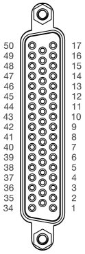
Automotive Communication Extender card pinouts
Table 6. Pinout - X2
| Pin |
Signal |
Pin |
Signal |
Pin |
Signal |
| 50 |
N.C. |
33 |
GND |
17 |
N.C. |
| 49 |
SPI1-CS2# |
32 |
GND |
16 |
SPI1-CS1# |
| 48 |
SPI1-CS0# |
31 |
GND |
15 |
SPI1-CLK |
| 47 |
SPI1-MOSI |
30 |
GND |
14 |
SPI1-MISO |
| 46 |
SPI2-CS1# |
29 |
GND |
13 |
SPI2-CS1# |
| 45 |
SPI2-CS0# |
28 |
GND |
12 |
SPI2-CLK |
| 44 |
SPI2-MOSI |
27 |
GND |
11 |
SPI2-MISO |
| 43 |
SPI3-CS1# |
26 |
GND |
10 |
SPI3-CS1# |
| 42 |
SPI3-CS0# |
25 |
GND |
9 |
SPI3-CLK |
| 41 |
SPI3-MOSI |
24 |
GND |
8 |
SPI3-MISO |
| 40 |
SPI4-CS1# |
23 |
GND |
7 |
SPI4-CS1# |
| 39 |
SPI4-CS0# |
22 |
GND |
6 |
SPI4-CLK |
| 38 |
SPI4-MOSI |
21 |
GND |
5 |
SPI4-MISO |
| 37 |
SENT1 |
20 |
GND |
4 |
SENT2 |
| 36 |
SENT3 |
19 |
GND |
3 |
SENT4 |
| 35 |
SENT5 |
18 |
GND |
2 |
SENT6 |
| 34 |
SENT7 |
|
|
1 |
SENT8 |
Table 7. Pinout - X3
| Pin |
Signal |
Pin |
Signal |
Pin |
Signal |
| 50 |
N.C. |
33 |
GND |
17 |
N.C. |
| 49 |
CAN1-N |
32 |
GND |
16 |
N.C. |
| 48 |
CAN1-P |
31 |
GND |
15 |
CAN2-N |
| 47 |
CAN3-N |
30 |
GND |
14 |
CAN2-P |
| 46 |
CAN3-P |
29 |
GND |
13 |
CAN4-N |
| 45 |
CAN5-N |
28 |
GND |
12 |
CAN4-P |
| 44 |
CAN5-P |
27 |
GND |
11 |
CAN6-N |
| 43 |
CAN7-N |
26 |
GND |
10 |
CAN6-P |
| 42 |
CAN7-P |
25 |
GND |
9 |
CAN8-N |
| 41 |
LIN1 |
24 |
GND |
8 |
CAN8-P |
| 40 |
LIN3 |
23 |
GND |
7 |
LIN2 |
| 39 |
LIN5 |
22 |
GND |
6 |
LIN4 |
| 38 |
LIN7 |
21 |
GND |
5 |
LIN6 |
| 37 |
FLEX1B-N |
20 |
GND |
4 |
LIN8 |
| 36 |
FLEX1B-P |
19 |
GND |
3 |
FLEX1A-N |
| 35 |
N.C. |
18 |
GND |
2 |
FLEX1A-P |
| 34 |
N.C. |
|
|
1 |
N.C. |
Automotive Communication Extender card firmware update
Firmware update of the ACE card is performed over ethernet through a dedicated
tool which can be accessed through the THCC Device Manager. Prior to starting the
firmware update procedure, the ACE card needs to be properly connected to the PC. In
order to do this, follow the steps below:
- Power up the card and connect it to the PC using an ethernet cable
- Configure the PC IP address in a way that it belongs to the same
subnet as the ACE card IP address. The ACE card has the following IP
address: 192.168.20.1xx, where the xx part is
inherited from the ETH ID rotary switch
- Make sure that the PC network connection is either configured as private, or has
inbound firewall rules that allow reception of UDP packages from remote port
56100 by local port 55100
Note: It is advised that no other devices are connected to the
same network as the ACE card while performing the firmware update.
After connecting the ACE card to the PC, consult the Syncing ACE Firmware in Device Manager
section for information on how to use the ACE Firmware Update Tool.