Additional information about pipeline graphical editor.
This section describes the structure and components of the Graphical editor used for
pipeline definition. Pipeline definition created
through the Graphical editor is equiualent to the definition created through the Script
editor.
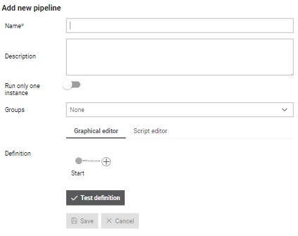
Figure 1. Script editor initial view in add pipeline dialog
Managing stages and jobs
Stages can be added by clicking on the button. Once a stage is added it will be presented in
the editor. Figure 2. Stage added to the pipeline through Graphical editor Every stage can be editted, duplicated or deleted by choosing appropriate
option from the menu that is opened by clicking on the icon in the Stage name header.
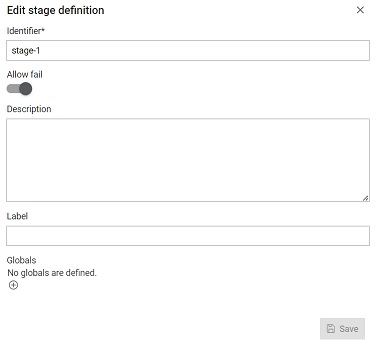
Edit Stage opens dialog through which information about the Stage can be changed.
Figure 3. Stage added to the pipeline through Graphical editor Jobs can be added to the stage by clicking on the button within the
stage graphical component. Clicking on the button will present dialog where desired
Job can be chosen from the list of all available Jobs. Once a Job is added it will
be presented within the chosen Stage. Same as for the Script editor, validation of
the definition created through the Graphical editor can be checked by clicking on
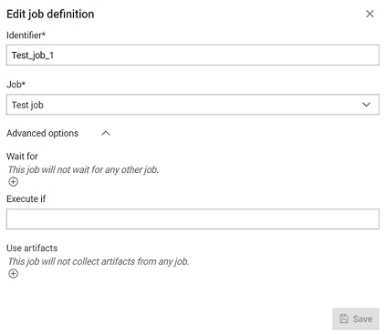
the button. Figure 4. Job added to the pipeline stage through Graphical editor Every job can be editted, duplicated or deleted by choosing appropriate
option from the menu that is opened by clicking on the icon in the Job name header. Edit
Job opens dialog through which information about the Job can be changed.
Options to include stage and pipeline reports are available in the dialog's advanced
settings. These options allow inclusion of reports from job execution to the stage
or pipeline aggregated report if there were any reports collected as allure-results.
For example, if a stage contains two jobs that both produce reports and the
Include reports into stage report option is toggled, both reports will be
combined into a single stage report, which will be available for preview from the
stage execution. The same applies to the Include reports into pipeline report
option. Figure 5. Edit job that is added to the pipeline through Graphical editor
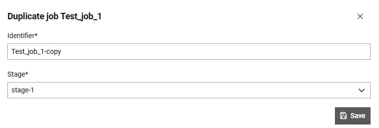
Duplicate
Job opens dialog through which new job name can be inserted and stage to which the
new job belongs can be selected.Figure 6. Duplicate job through Graphical editor
Note: When using the Graphical editor, stage order within the Pipeline
can be changed using drag and drop. The same applies to modifying order of the jobs within the stage.
Changing between the editors
Switching between the editors will result in preview of equiualent pipeline definition
ether within Script or Graphical editor, depending on the choosing.
Note: Switching between two editors will give expected output if the definition was previously saved.
Same definition shown through both Script and Graphical editor
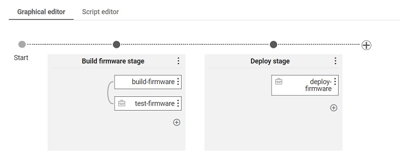
In this basic example of a pipeline definition, it is assumed that there are jobs
named Job Build Firmware, Job Test Firmware and Job Deploy
Firmware. Also, it is needed to add first_param and
second_param.
Figure 7. Basic pipeline example shown in graphical editor
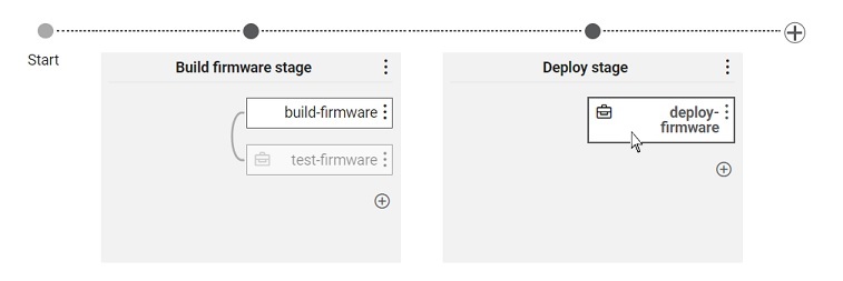
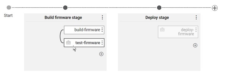
Graphical editor will show dependencies between the jobs if those exist. In the
example, job with the label test-firmware has wait defined which
specifies that build-firmware needs to be finished before
test-firmware starts its execution. When hovering over a Job that has
wait defined, editor will stand out Job that is being waited and
connection (line) between them, while others would get greyed out. Figure 8. Dependency between two jobs where one is waiting for the other
oneIn the example below, job with the label deploy-firmware has
use-artifacts defined which specifies that deploy-firmware is
using artifacts from the Job with label build-firmware. If a Job has
use-artifacts defined, icon will be shown next to its name. When hovering over the
icon, editor will stand out that current Job and the Job from which current one is
using the artifacts, while others would get greyed out. Figure 9. Dependency between two jobs where one is using artifacts from the other
one
Note: All options shown in the images or mentioned throughout the section
about the Graphical editor are equivalent
to the options with the same name explained in the
pipeline definition section.
 button. Once a stage is added it will be presented in
the editor.
button. Once a stage is added it will be presented in
the editor. 
 in the Stage name header.
Edit Stage opens dialog through which information about the Stage can be changed.
in the Stage name header.
Edit Stage opens dialog through which information about the Stage can be changed.
 button within the
stage graphical component. Clicking on the button will present dialog where desired
Job can be chosen from the list of all available Jobs. Once a Job is added it will
be presented within the chosen Stage. Same as for the Script editor, validation of
the definition created through the Graphical editor can be checked by clicking on
the
button within the
stage graphical component. Clicking on the button will present dialog where desired
Job can be chosen from the list of all available Jobs. Once a Job is added it will
be presented within the chosen Stage. Same as for the Script editor, validation of
the definition created through the Graphical editor can be checked by clicking on
the  button.
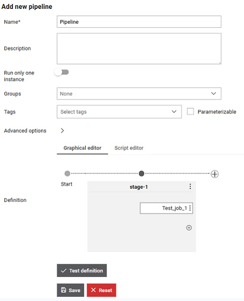
 will be shown next to its name. When hovering over the
icon, editor will stand out that current Job and the Job from which current one is
using the artifacts, while others would get greyed out.
will be shown next to its name. When hovering over the
icon, editor will stand out that current Job and the Job from which current one is
using the artifacts, while others would get greyed out.