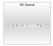
HV Source
Description of the HV Source component in Schematic Editor.
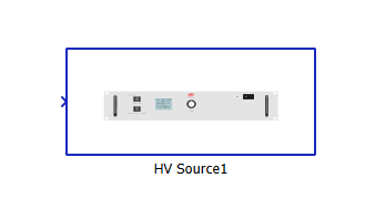
HV Source Description
The HV Source component, shown in Figure 1, is a signal processing based component from the HIL Interfaces library category. It can be used to remotely control an HV Source device. It can be used to observe measured voltage on the output of the device. This component must be used together with CAN FD Setup component.
General (Tab)
- Device ID
- This parameter should match the HIL device setting to which the HIL Connect is connected. This is important only in multi-HIL simulations. Available options are from 1 to 15.
- Voltage set control
- "Signal from model" sets the control method for output voltage of the targeted device to a signal processing input of a HV Source component, which should be connected to the controlling signal from the model.
- "Signal chooser" is selected, new property "Signal" will appear and user should select controlling signal from signal chooser to sets the control output voltage of the targeted device.
- Output voltage of the targeted device can also be overridden from SCADA panel since this component has its own SCADA Widget.
- CAN controller
- Sets CAN controller for internal CAN FD Send and Receive components. Available options are CAN1 and CAN2.
- Execution rate
- The signal processing time step.
Settings (Tab)
- Upper Voltage Limit
- This parameter is used to limit the maximal output voltage which can be set on the output of the device. Maximal possible output value is 1500 V.
- Lower Voltage Limit
- This parameter is used to limit the minimal output voltage which can be set on the output of the device. Minimal possible output value is -1500 V.
Configuration of HV Source and CAN FD Setup components
The HV Source component should always be used alongside with CAN FD Setup component. The parameters of CAN FD Setup should be set as described below.
- Chosen CAN controller execution rate should be the same as the execution rate of the HV Source component.
-
CAN baud rate (Nominal/Data) should be set to 500K/500K bit/s.
SCADA Widget for HV Source
The HV Source component has its own SCADA Widget shown in Figure 2. Whenever HV Source is used, this SCADA Widget should be included in the model SCADA Panel. When On/Off is checked, the output of an HV Source will be enabled; otherwise it will be disabled. By checking the Override box, the voltage applied at the output of the HV Source device will be the value entered in Override Voltage. When this check box is unchecked, the control voltage is defined by the HV Source component's Control property. The button Request Voltage Measurement is used to request a measurement from the HV Source device outputs.