Description of how to enable, disable and use the alignment assistant
When moving components in Schematic Editor,
guidelines in the form of horizontal or vertical dot-dashed lines are displayed when
certain items align. This feature can be enabled or disabled using the checkbox in the
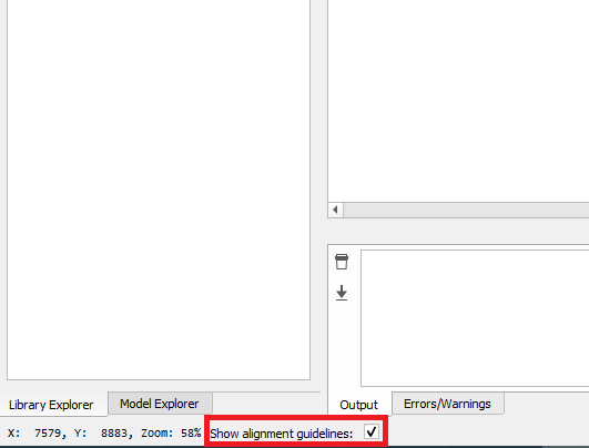
Schematic Editor status bar (Figure 1).
Figure 1. Alignment guidelines checkbox location
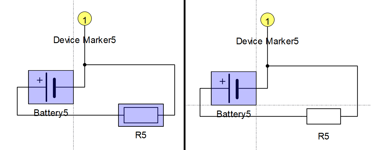
Guidelines will only be shown between items that are selected and items
that are not selected. Items that are aligned but are part of the same
selection will not have guidelines drawn between them.Figure 2. Guidelines between a single and multiple selected components
Guideline types
There are three types of alignment guidelines:
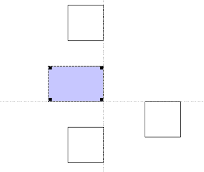
Edge guidelines - Drawn when the bounding box of components align.
Figure 3. Edge guidelines
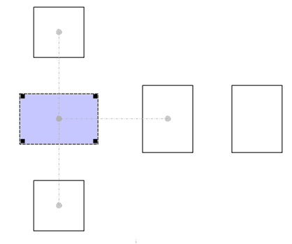
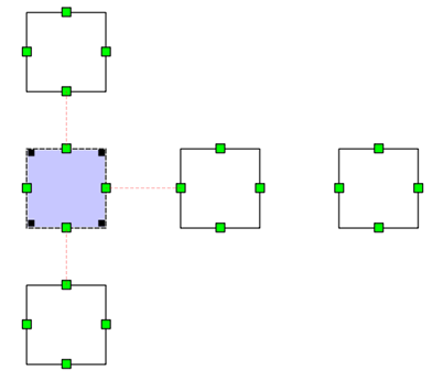
Center guidelines - Drawn when the center of components align. Displayed for the closest aligned component, per direction.
Figure 4. Center guidelines
Terminal guidelines - Drawn when the terminals of the components align. Displayed for terminals of the closest aligned component, per direction.
Figure 5. Terminal guidelines
Note: When terminal guidelines are visible, edge guidelines are hidden, and only perpendicular center guidelines are displayed.