Electrical
Electrical properties for the HIL Electric Vehicle Charging Interface
Electrical diagram
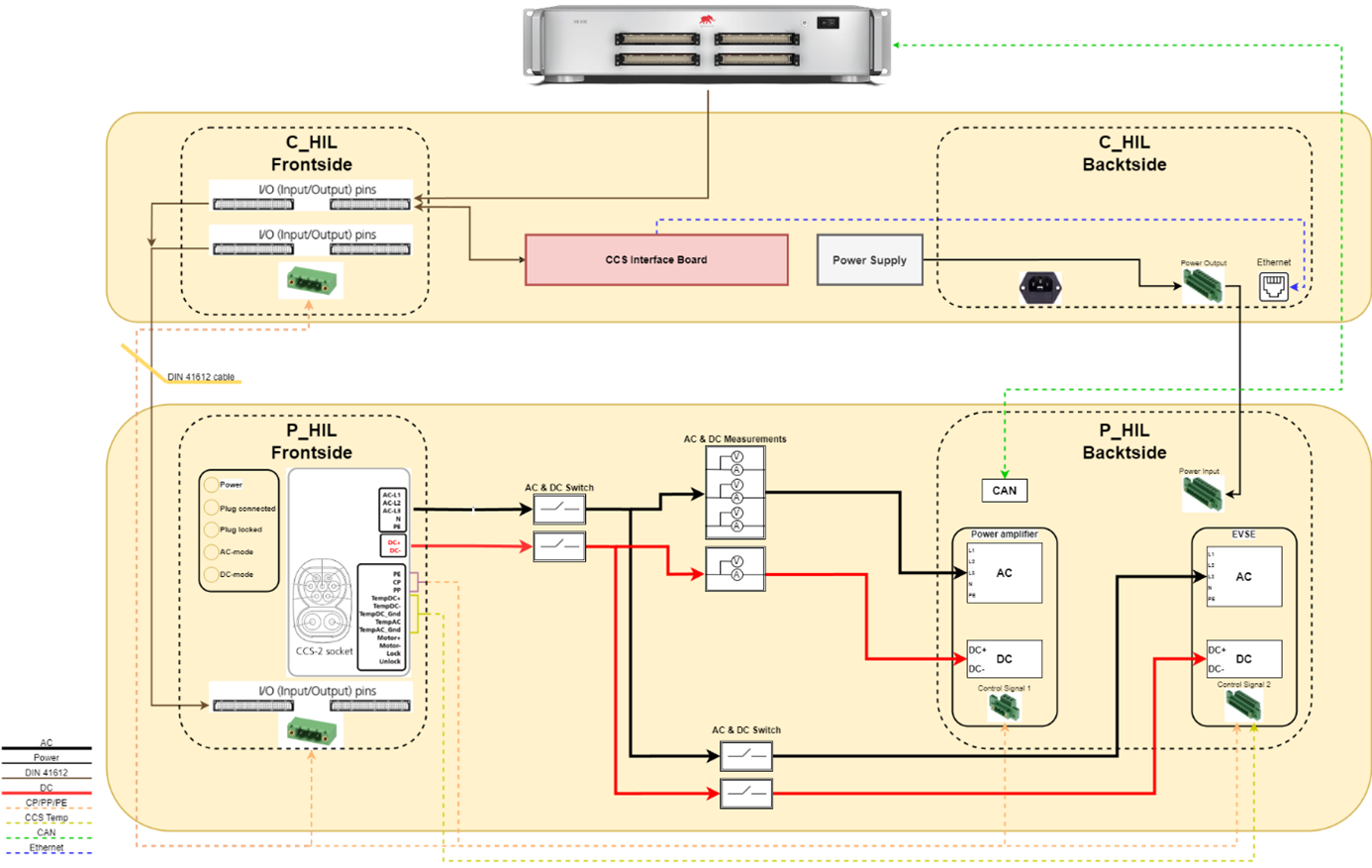
- The P-HIL and C-HIL devices are powered by a standard C14 mains connector, located on the rear side of the C-HIL Connect, for connecting the device to the power grid.
- The P-HIL Connect is exclusively powered through the C-HIL Connect via an eight-pin Phoenix connector labeled as Power Input and Power Output, as described in the Power Supply section.
The device signals are interconnected using DIN cables, where the upper row on the C-HIL Connect is directly connected to the HIL device, while the lower row is connected to the DIN connectors of the P-HIL Connect. Further details on all other signals can be found in Figure 1, and in the Detailed description.
Power Supply
The C-HIL Connect Interface device is connected to a standard power outlet via the C14 power connector, which has an embedded 8 A fuse.
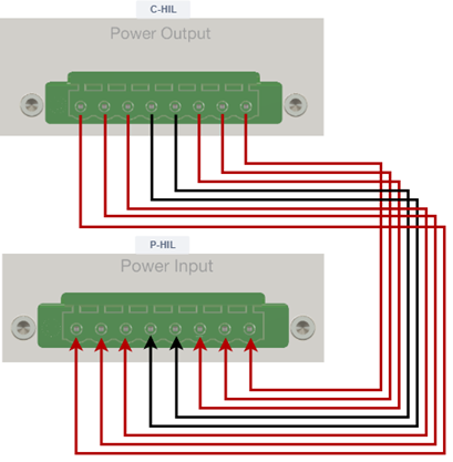
The P-HIL Connect Interface is in turn powered through the C-HIL Interface. This is done by connecting the Power Output connector on the rear side of the C-HIL Connect Interface hardware device with the Power Input connector on the rear side of the P-HIL Connect Interface device, as shown in Figure 2.
The C-HIL Interface supplies power to the P-HIL Interface on the following voltage levels: -24V, +24V, +12V, GND. The voltage levels are intended only for powering the P-HIL device, and cannot be used for other needs.