Dynamic Grid Fault
Description of the Dynamic Grid Fault component in Schematic Editor.
Description
The Dynamic Grid Fault component emulates a fault on a three phase grid using ideal switches. The chosen fault can be selected through either a SCADA input (in real-time/VHIL simulation) or a signal processing input. This is chosen by the Properties window of the component. Each of the eleven available fault types have their own code number (Table 1) that is used to apply the fault during simulation execution. Phase to phase and phase to neutral resistances can be defined using the Properties window; by default they are set to 0.1 Ω. Phase to neutral resistance must be greater or equal to half of the defined phase to phase resistance: . Depending on the chosen fault type, the states of the ideal switches in the component are controlled using the state machine implemented in the C function block. In real-time/VHIL simulation, the internal structure of the component with the selected SCADA input is shown in Figure 2. The digital signal processing part is executed with an execution rate specified in the Property window.
| Fault type | Fault code number |
|---|---|
| A-N (Phase A to Neutral) | 5 |
| B-N (Phase B to Neutral) | 2 |
| C-N (Phase C to Neutral) | 1 |
| A-B (Phase A to Phase B) | 8 |
| A-C (Phase A to Phase C) | 6 |
| B-C (Phase B to Phase C) | 3 |
| A-B-N (Phase A to Phase B to Neutral) | 9 |
| A-C-N (Phase A to Phase C to Neutral) | 7 |
| B-C-N (Phase B to Phase C to Neutral) | 4 |
| A-B-C (Phase A to Phase B to Phase C) | 10 |
| A-B-C-N (Phase A to Phase B to Phase C to Neutral) | 11 |
| NO FAULT | 0 |

Internal digital measurements of the Dynamic Grid Fault component
| Digital output variable name | Description |
|---|---|
| (name).S1.feedback | Digital feedback of the Phase A switch |
| (name).S2.feedback | Digital feedback of the Neutral switch |
| (name).S3.feedback | Digital feedback of the Phase B switch |
| (name).S4.feedback | Digital feedback of the Phase C switch |
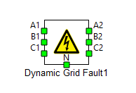
Ports
- A1 (electrical)
- Left AC side port - Phase A
- B1 (electrical)
- Left AC side port - Phase B
- C1 (electrical)
- Left AC side port - Phase C
- A2 (electrical)
- Right AC side port - Phase A
- B2 (electrical)
- Right AC side port - Phase B
- C2 (electrical)
- Right AC side port - Phase C
- N (electrical)
- Neutral point port
- Fault in (signal)
- Available only if Control method is set to Signal input
Parameters
- Control method
- Specifies the control method with available option/s:
- SCADA input(in real-time/VHIL simulation)
- Signal input
- Specifies the control method with available option/s:
- Phase to phase fault resistance
- Specifies phase to phase fault resistance.
- Phase to neutral fault resistance
- Specifies phase to neutral fault resistance.
- Execution rate
- Type in the desired signal processing execution rate. This value must be compatible with other signal processing components of the same circuit: the value must be a multiple of the fastest execution rate in the circuit. There can be up to four different execution rates. To specify the execution rate, you can use either decimal (e.g. 0.001) or exponential values (e.g. 1e-3) in seconds. Alternatively, you can type in ‘inherit’ in which case the component will be assigned execution rate based on the execution rate of the components it is receiving input from.
- CPU core
- Sets the CPU marker's value for the signal processing part of the sub-circuit.