Introduction | How do digital substations work?
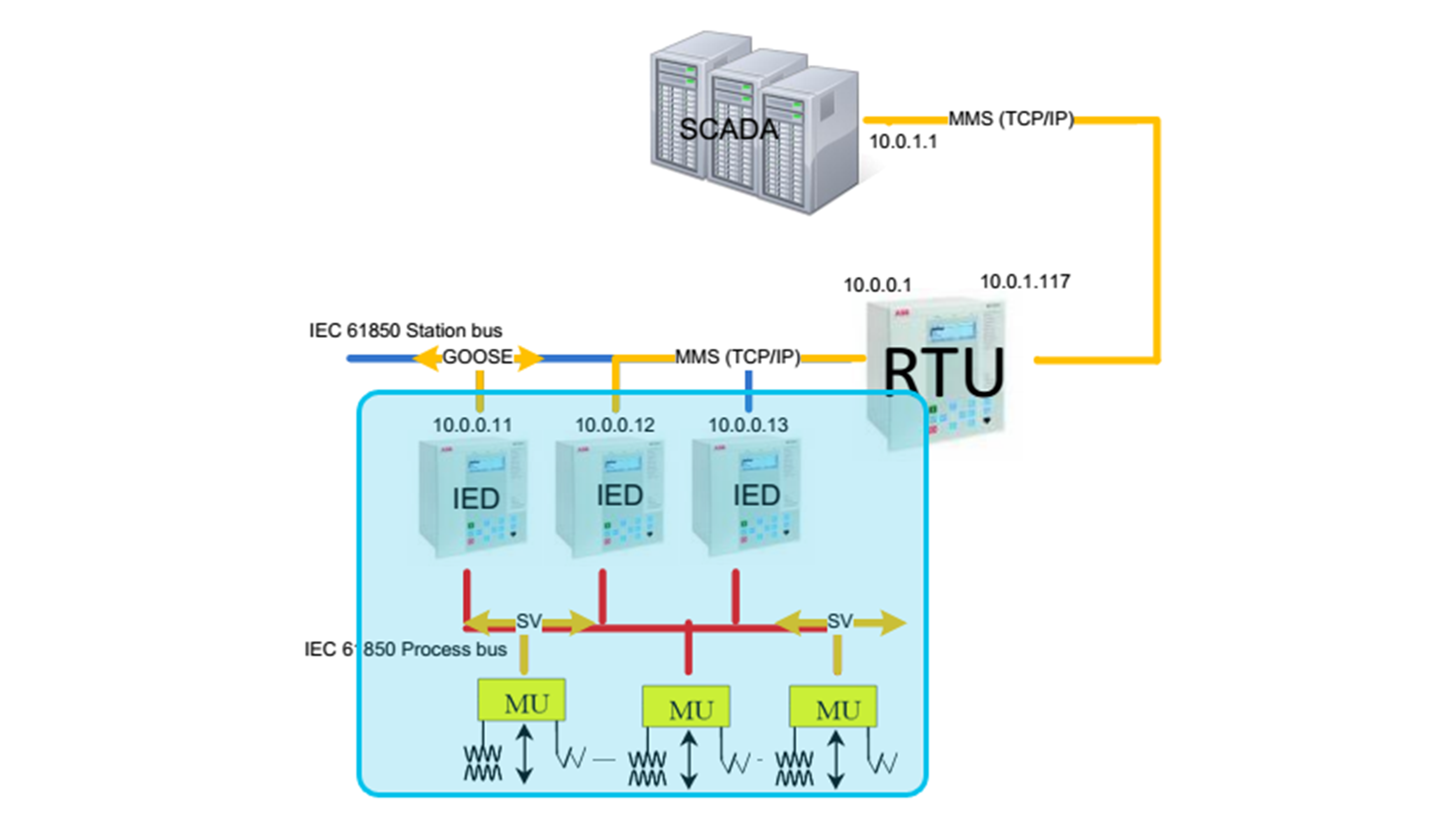
The evolution of power systems protection and control has seen a significant shift towards digitalization. Reducing resource requirements, improving asset utilization, and increasing situational awareness are just a few benefits brought by the digitalization of substations, particularly with the implementation of the IEC 61850 standard. This standard facilitates advanced digital communication protocols within substations, allowing for process bus and station bus communication between Intelligent Electronic Devices (IEDs) and higher-level control systems. The process bus enables moving data from the primary equipment, like a circuit breaker or instrument transformer, to protection relays in automation devices in the control room. The process bus communication is facilitated through Generic Object-Oriented Substation Event (GOOSE) messages and Sampled Values (SV) protocols. The Manufacturing Message Specification (MMS) protocol for station buses ensures effective data exchange between the Supervisory Control and Data Acquisition (SCADA) system and the substation devices.
These advancements enhance the efficiency and reliability of substation operations, enabling comprehensive testing at the substation level rather than at individual IED device level.
The key components of a digital substation include:
- Standardized Communication: The IEC 61850 standard ensures interoperability and standardization across devices, allowing seamless integration and communication within the substation.
- High-Availability Seamless Redundancy (HSR) and Parallel Redundancy Protocol (PRP): These redundancy mechanisms ensure continuous operation and high availability, allowing the substation to maintain functionality in case of network or component failures.
- Precision Time Protocol (PTP) and Grand Master Clock (GMC): These components provide accurate timing for data sampling and event recording, ensuring that all devices in the substation operate in sync.
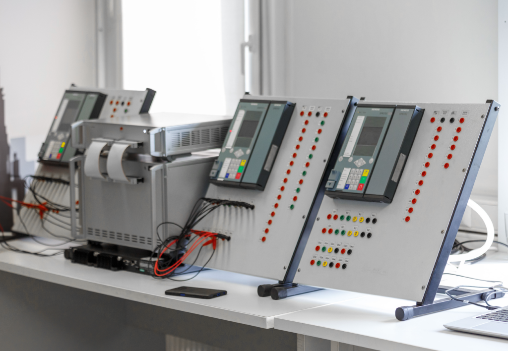
- Intelligent Electronic Devices (IEDs): These devices communicate using GOOSE messages and Sampled Values (SV), enabling real-time data exchange, and improving the accuracy of protection and control mechanisms.
- Merging Units (MUs): Convert analog signals from conventional measuring transformers into IEC 61850 digital signals, which are then processed by IEDs.
- Low Power Instrument Transformers (LPITs): Provide digital interfaces that are immune to magnetic core saturation, offering more reliable measurements.
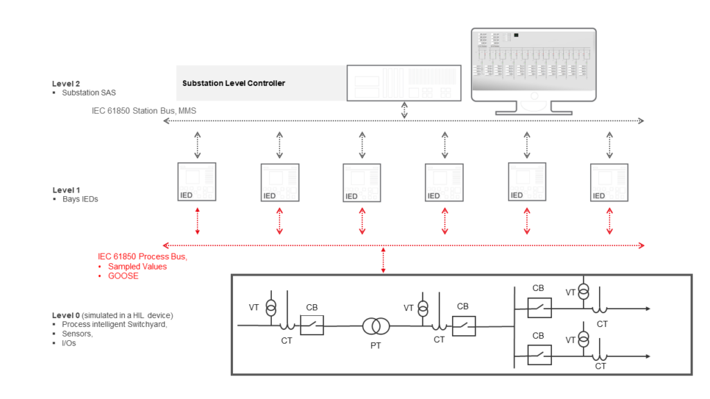
The primary equipment in a digital substation are power transformers (PTs), circuit breakers (CBs), and instrument transformers (CTs/VTs). These are essential for stepping down/up voltage levels, protecting circuits, and measuring electrical parameters, respectively. Redundancy mechanisms, time synchronization, and cybersecurity measures are integrated throughout the network to ensure high availability and data protection.
HIL Testing | How can HIL devices be used in digital substations?
There are multiple applications and reasons for using a Hardware-in-the-Loop (HIL) system in the everyday work of a substation protection engineer:
- System Protection Testing: HIL technology allows for comprehensive testing of the protection system within a digital substation. By simulating faults at various points in the substation, engineers can evaluate the functionality, performance, sensitivity, and selectivity. For instance, overcurrent and directional overcurrent protections can be tested under different fault conditions, ensuring they respond appropriately.
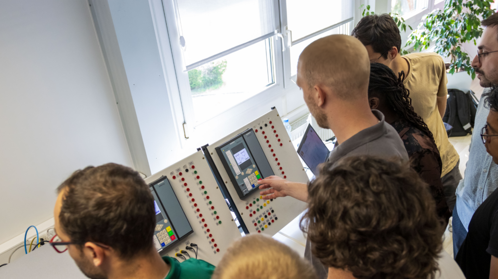
- Training for Engineers: HIL systems provide an invaluable training platform for engineers and technicians. The ability to simulate real-world scenarios in a controlled environment, repeatably, and safely allows trainees to rapidly gain man years’ worth of practical experience in handling substation automation systems in a short time. This is particularly useful for training engineers using new technology and protocols without risking operational safety.
- Development and Commissioning: During the digital substation development phase, the HIL setup can be used to test protection and control algorithms before there is even any hardware available and far ahead of the field deployment. During commissioning, HIL systems enable Factory Acceptance Testing (FAT) and Site Acceptance Testing (SAT), ensuring that all systems function correctly before being brought online.
HIL Benefits | Why use HIL for substation automation system testing?
Hardware-in-the-Loop (HIL) technology represents a breakthrough in testing and training for Substation Automation Systems (SAS). HIL integrates real-time simulation capabilities with the physical components of the substation, providing a virtual environment where various scenarios can be tested without the need for physical disruptions.
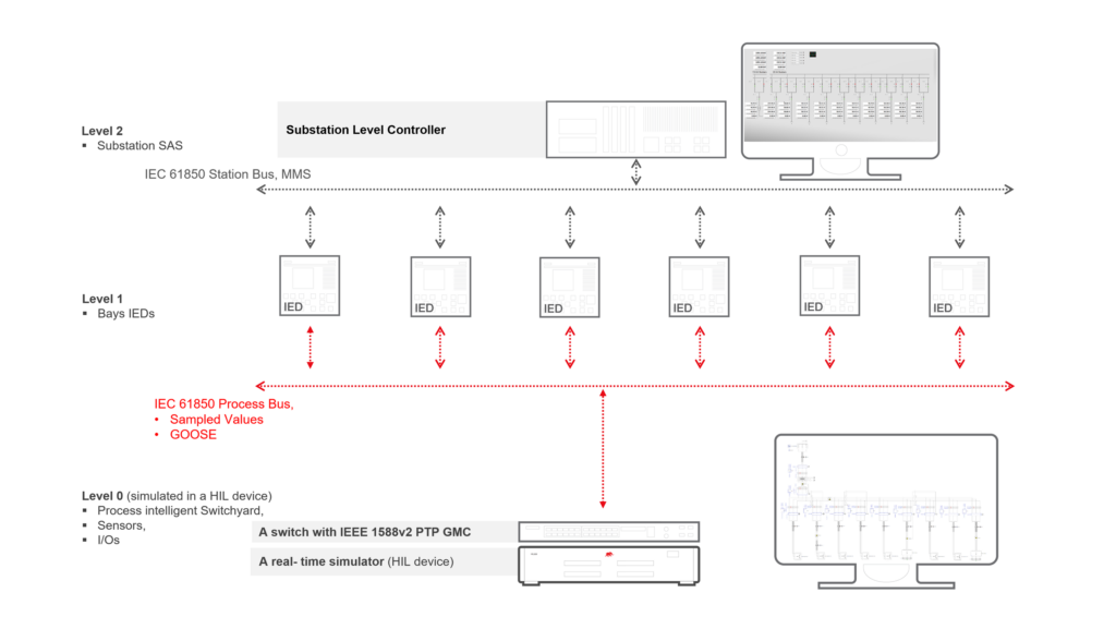
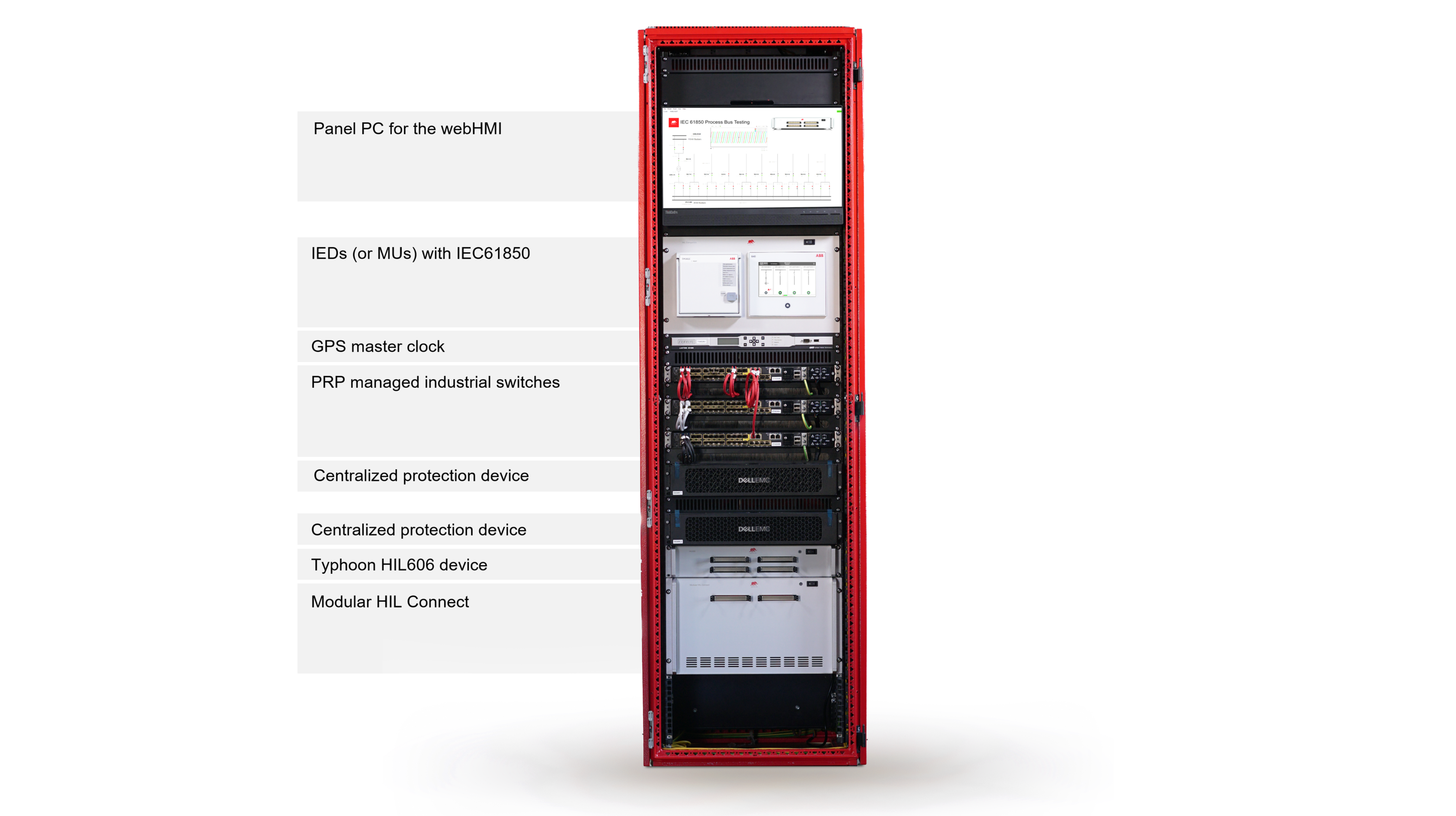
The test environment includes an industrial computer (server) that represents the SCADA system for control and monitoring, multiple IEDs under test, a network with a switch (with or without IEEE1588v2 PTP), a GPS master clock for time synchronization, and a HIL simulator with a digital twin of the substation.
The key features of HIL testing are:
- Real-Time Simulation: HIL systems can simulate the entire power processing part of the substation with connected power system, including primary equipment like transformers and circuit breakers. This allows for the testing of protection schemes by emulating various fault conditions and standard operating scenarios.
- Communication Protocols: Utilizing IEC 61850, HIL systems can send and receive GOOSE messages and SVs, emulating the actual communication between substation devices with high-fidelity.
- Integration with SCADA Systems: HIL setups often include Supervisory Control and Data Acquisition (SCADA) systems, managing and controlling substation operations through Manufacturing Message Specification (MMS) communication.
Case Study | Medium-voltage substation model testing
Cost and time efficiency are major concerns in traditional testing methods, which often require expensive field tests and result in downtime. HIL enables virtual and fully automated testing, which significantly reduces costs. Furthermore, HIL testing enhances safety and mitigates risk by increasing the test coverage.
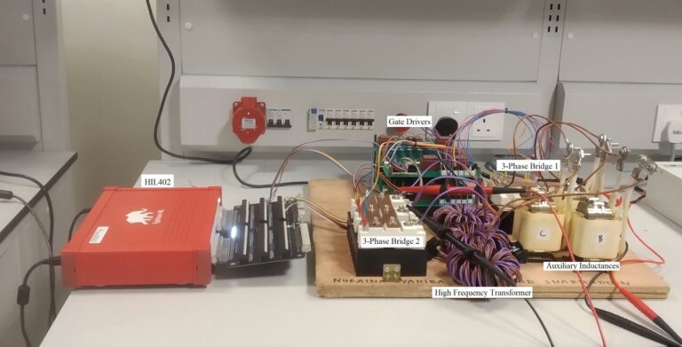
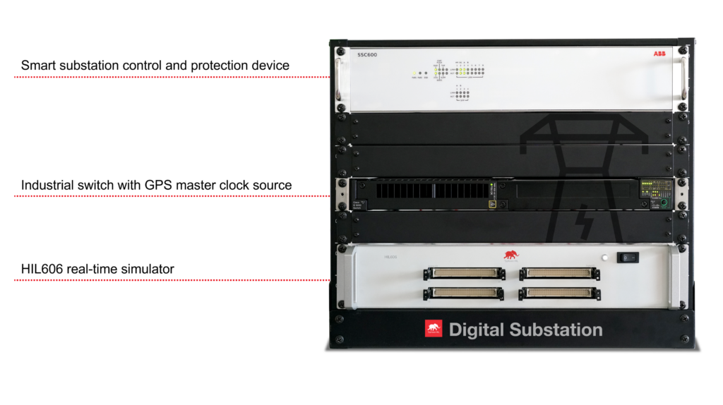
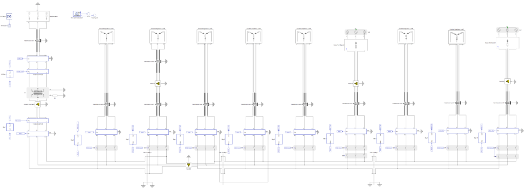
A detailed case study involved the development of a mathematical model of a substation and HIL setup. The substation model included ten bays, with specific points where faults could be introduced to test the protection systems. Various types of faults, such as phase-to-phase and ground faults, were simulated to assess the response of the protection devices. The hardware setup consists of a smart centralized protection device, an industrial switch with GPS master clock source capabilities, and a HIL606 device.
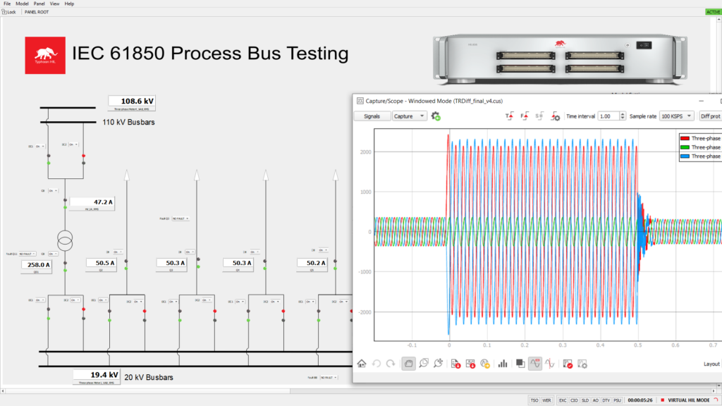
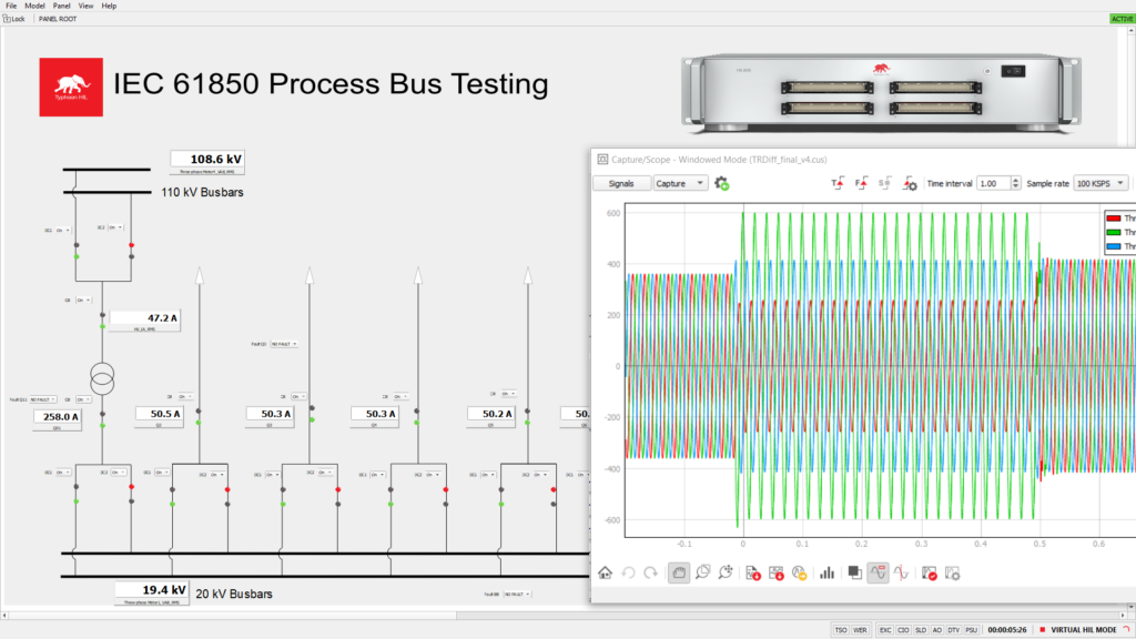
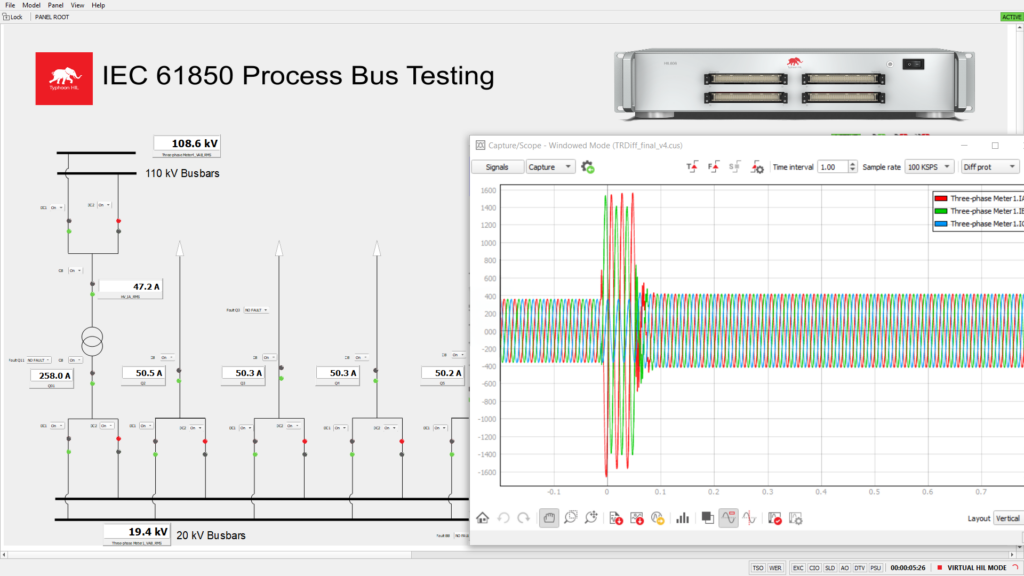
These are the experimental results for the phase currents on the secondary side of the transformer:
- Overcurrent Protection: By simulating an overcurrent fault in one of the bays, the system’s response time and accuracy were measured. The protection device successfully tripped the circuit breaker upon detecting the fault.
- Zero-Sequence Overcurrent Protection: A ground fault was introduced, and the system’s ability to isolate the fault without affecting other parts of the substation was tested. The protection device tripped the appropriate circuit breakers, demonstrating the selectivity of the system.
- Directional Overcurrent Protection: For bays with distributed generation, directional overcurrent protection was tested to ensure that faults were isolated correctly, preventing back-feeding into the grid.
Conclusion | Benefits of HIL testing
The introduction of HIL technology in the testing, lifecycle maintenance, and personnel training for digital substations marks a significant advancement in the field of intelligent digital power systems. Indeed, by providing a robust platform for real-time simulation and testing, HIL enhances the reliability, safety, and efficiency of digital substation operations. As the power industry continues to evolve, the role of HIL in ensuring seamless operation of digital substations will become increasingly vital. To learn more, watch our demo video on Model-Based HIL Testing Solution for a Digital Substation or schedule a free demo with our team where we can address questions for your specific application case.
Credits
Author | Simisa Simic
Visuals | Milica Obradovic, Karl Mickei
Editor | Ivan Celanovic, Dovlyn Curtis, Debora Santo
Acknowledgments | We thank Prof. Zoran Stojanović and the University of Belgrade School of Electrical Engineering for their collaboration concerning the development of this Digital Substation testing solution.