Introduction | The Microgrid & DER Controller Symposium
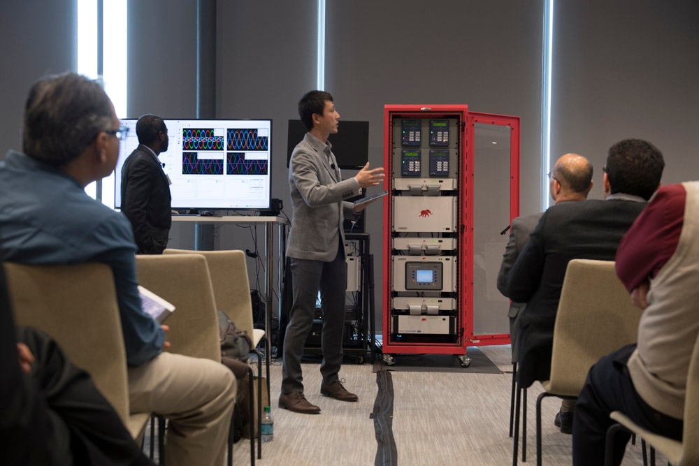
At the Microgrid & DER Controller Symposium 2017, the brainchild of Erik Limpaecher from the MIT Lincoln Laboratory, the ultra-high fidelity controller Hardware in the Loop (HIL) was in the spotlight, and it was glowing. It won the hearts and minds of all power engineers present.
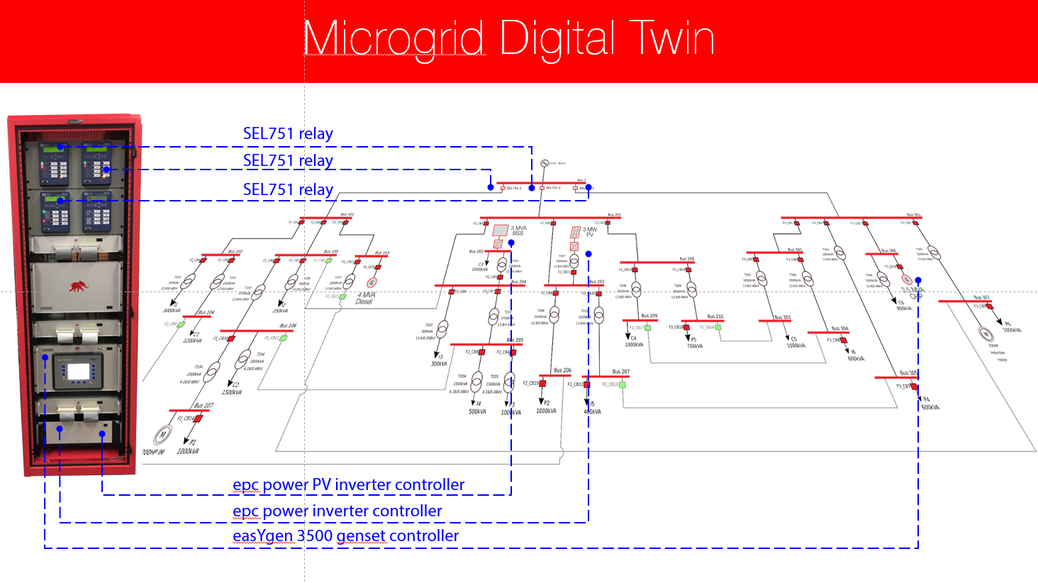
At the workshop center stage, the real, unadulterated industrial microgrid controllers — from Eaton, GE, SEL, and Schneider — were in action. They were directly interfaced with and controlled the Microgrid Controller-HIL Testbed running real-time simulation comprising 3 feeders with 24 busses, one diesel generator, one natural gas generator with combined heat and power, battery storage, PV inverter, and numerous loads.
Microgrid controllers had to deal with a spectrum of disturbances including various faults; irradiance profiles, load profiles, and Distribution Management System (DMS) requests to microgrid controllers (e.g. to export active/reactive power, to island, etc.)
While working alongside microgrid controller vendors, in preparation for the symposium demo, we learned 6 key lessons that will help ease your future design, test, validation, and integration pains:
- Thou shalt use HIL.
- Start simple.
- Configure and test communications with HIL models.
- Test with real controllers in the loop to build confidence.
- Test relentlessly.
- Test Microgrid controller cyber security.
1. Thou shalt use HIL
Designing and testing microgrid controllers is difficult as it is. Designing and testing microgrid controllers without the right tools is close to impossible. Today, microgrid controller design, testing, and commissioning for vendors without the HIL platform looks like this:
- Simulate the power stage using an offline simulator (most often steady state power flow calculation) and obtain protection settings (based on limited steady state analysis).
- Use the results of the offline simulation as a starting point to program and configure the microgrid controller.
- Go to the field and try to make the microgrid controller work.
- Fight with communications between microgrid controller and DERs while in the field commissioning.
- Test basic controller functionality and protection and commission the microgrid.
- Hope that the call, saying the microgrid is down, doesn’t come too soon.
With the HIL microgrid testbed controller design and testing, the process looks very different:
- Build a microgrid power stage model; use virtual HIL or an offline simulator and obtain key microgrid parameters.
- Use unit test HIL models, for individual DERs, to configure and test microgrid controller communications. One DER at a time. (And all this while comfortably enjoying the warmth of your office.)
- Test the complete microgrid controller using a real-time HIL model of the microgrid (without any real controllers in the loop – as the whole microgrid is simulated including controllers).
- Add controllers in the loop, one by one, and continue testing. Test starting from basic controller functionality and protection all the way to complex mode switching etc.
- Casually go to the microgrid site, download controller firmware to the site controller, and wrap up microgrid controller commissioning with confidence.

2. Start simple
Microgrid is a complex system. On one hand communications between microgrid controllers and DERs and relays are complex (multiple communication protocols) and poorly standardized, and on the other hand dynamic behavior of generators and loads gives rise to complex system behavior.
Hence, when designing and testing controls, one ought to start with a single DER model (e.g. battery storage, genset, etc.) and test out communications first, calibrate measurements, test setting reference values, and toggling states. Only then move on to test dynamics using the same simple Build level 0 unit tests.
3. Configure and test communications with HIL models
Validated ultra-high fidelity models for microgrid components, including dynamic models of DERs and relays, are paramount. Ultra-high fidelity simulation models have two sides of the coin:
- Communication model fidelity, and
- Dynamic model fidelity.
4. Test with real controllers in the loop to build confidence
When all the unit tests are done and communication protocols are up and running and fully validated it is time to move on to Build Level 1 (BL1) models.
Build level 1 means that we have real controllers in the loop with the simulation. For example: we can have a real relay in the loop, a real inverter controller, a real genset controller, etc.
5. Test relentlessly
Once we have built and tested the microgrid controller with Build level 0 and Build level 1 models we are ready to dive into comprehensive system-level testing.
In this phase, we start building a library of automated test sequences that include fault scenarios, different system disturbances, and various load and irradiance profiles.
6. Test microgrid controller cyber security
The final phase, before commissioning, is the testing of the microgrid controller and communication cyber security. Controller Hardware in the Loop is a perfect testbed to test and validate cyber security and the potential impact of a security breach.
Indeed, since all controllers are in the loop the communication and control architecture is identical to the one in the final hardware installation. Hence, the controller HIL presents a perfect sandbox for testing and validation of cyber security.
Conclusion | May we live in interesting times
As a civilization, we are only at the beginning of a massive transformation that will completely re-engineer the way we produce, distribute, and use electrical energy. Indeed, we are in the process of transforming our energy networks into more resilient, more flexible, and more sustainable systems through the integration of distributed energy resources, the introduction of renewable energy generation, and advanced distributed controls and coordination.
The only way to achieve these goals will be through the rapid adoption of new electronic design automation (EDA) tools, including the Ultra-high Fidelity Hardware in the Loop (HIL) real-time simulation.
Credits
Author | Ivan Celanovic
Visuals | Typhoon HIL
Editor | Debora Santo