Introduction | PMSM performance advantages in EV drive units
The path to making electric vehicles competitive with gas-powered ones has been full of roadblocks, mainly regarding efficiency, driving range, and cost. To overcome them, innovations in every aspect of the electrified powertrain are constantly emerging. In the drive unit, in particular, Permanent Magnet Synchronous Motors (PMSMs) are a trending technology to reduce the motor size and weight while boosting efficiency and power density. But why exactly have they been considered a silver bullet for EV drive units lately?
A key advantage of PMSMs is that they use permanent magnets to generate rotor excitation, with essentially no electrical current circulating in the rotor. This reduces core losses and means that more power can be generated with a smaller motor volume. On average, PMSMs are two to three times more power dense than induction motors, providing an efficiency gain of 2-5% depending on motor nominal power and weight reduction. Other benefits include improved heat management, higher efficiency for a larger frequency range, and better torque control.
However, as promising as these benefits sound, there are some challenges in adopting PMSMs that are related to development costs and the complexity of controlling these machines.
Challenges | Complex controls and costs of PMSMs
Permanent magnets used in PMSM rotors are composed of expensive rare earth materials, such as neodymium-iron-boron, making PMSMs more expensive than induction motors. In addition, Neodymium magnets should not operate above a certain temperature threshold, since their magnetism drops as the temperature rises. This can affect motor efficiency and sometimes result in permanent rotor demagnetization. Therefore, temperature control is vital for PMSM applications.
In addition, the PMSM stator must be driven with a pure sinusoidal voltage with no torque ripple to achieve high efficiencies, requiring more complex control techniques, such as Field Oriented Control (FOC), flux weakening, and sensorless control. These controllers rely on precise speed measurements to ensure efficiency related to synchronous operation. Thus, angular position, measurement, or estimation is required – adding one more piece to this complex control solution.
Taken together, this means that developing PMSMs for EV applications requires highly accurate control development testing to ensure reliability prior to building costly physical prototypes. To overcome these challenges, electric car manufacturers can take advantage of real-time Hardware-in-the-Loop (HIL) simulation and finite element modeling (FEM) to validate controls for PMSMs more efficiently.
HIL Testing | PMSMs for EV drivetrains
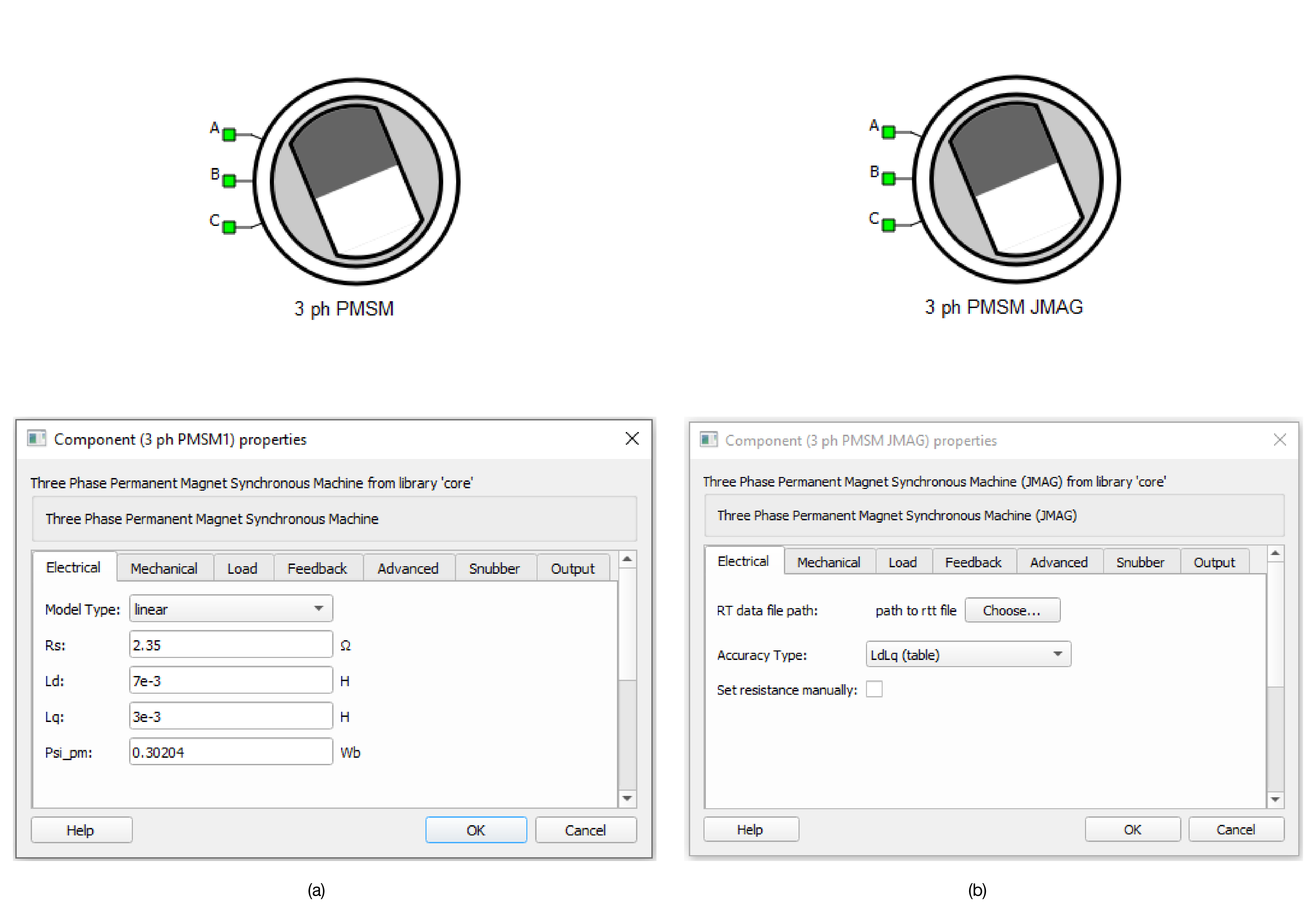
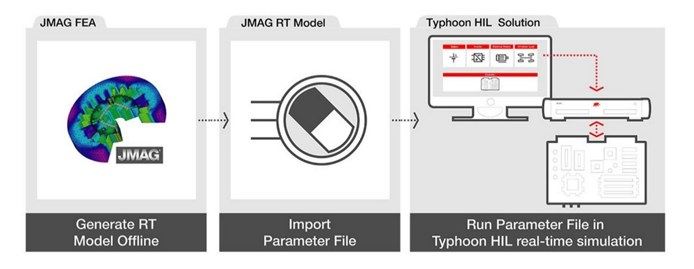
The Typhoon HIL Component Library offers several drag-and-drop options to easily create a digital twin model of PMSMs (See Fig. 1). The first (Fig. 1a) is the Three Phase Permanent Magnet Synchronous Machine component, which requires you to provide data from the motor datasheet. The second option (Fig. 1b) is the Three Phase Permanent Magnet Synchronous Machine (JMAG), which takes advantage of Typhoon-JMAG integration to achieve ultra-high model fidelity. To configure this component, you must upload the model files generated by the JMAG-RT finite element analysis (FEA) tool (see Fig. 2). FEA-based models provide more accurate mechanical, electrical, and thermal operational data of motors, making test results more impactful and realistic.
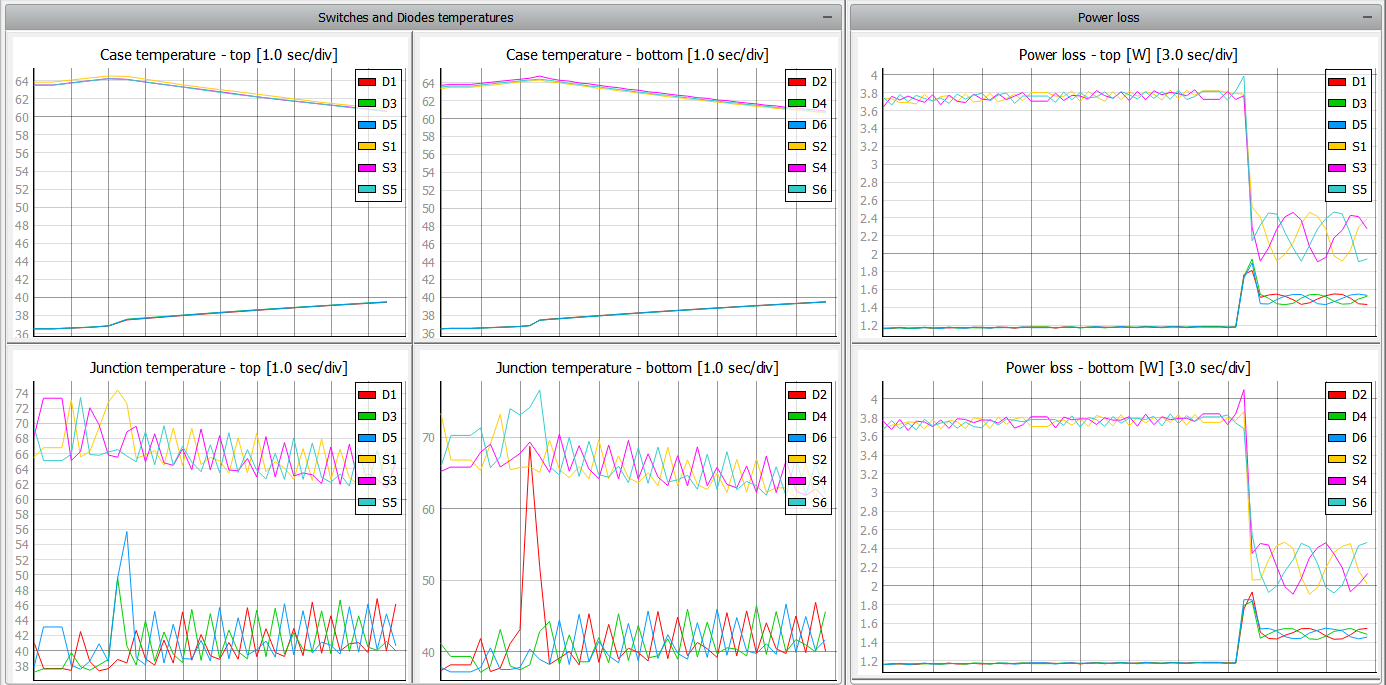
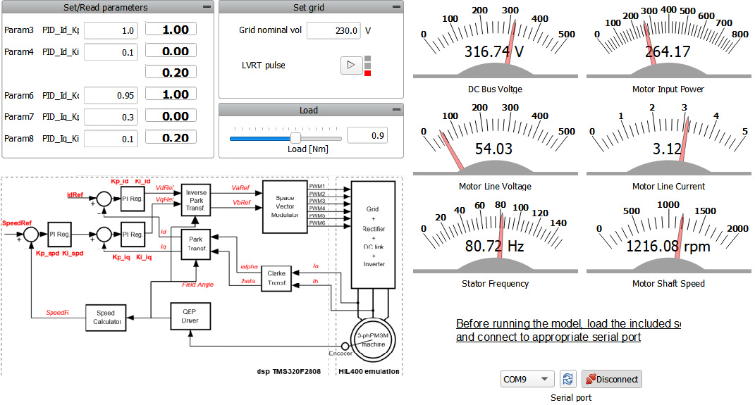
Test relevance is highly dependent on the power electronics model fidelity. To help with that, the Typhoon HIL Component Library provides an extensive selection of power converter components (i.e. three-phase inverter), which you can drag and drop to start using them in your drive unit application. With these models, you can individually measure the power losses and operational temperatures of semiconductors. Figure 3 presents the results of temperature and losses shown in a SCADA interface of a three-phase inverter.
After setting up the high-fidelity models for the drive unit components, it’s time to add the control system for the PMSM. Typhoon HIL gives you multiple options to implement controllers, including signal-processing components, C function, or running the controller in the Digital Signal Processor (DSP) that will be used in the final product. Figure 4 presents an example SCADA of a PMSM application using a three-phase inverter controlled by an external Texas Instruments DSP running a Field Oriented Controller.
Combining FEM models with powerful Typhoon HIL solutions gives you information about temperature, losses, spatial harmonics, and efficiency from the motor and power electronics. The benefits do not stop there though. You can take advantage of automated tests to continuously test PMSM control through a wide range of operating scenarios, providing meaningful reports, and accelerating product development.
Credits
Text | Cassiano F. Moraes, Heitor J. Tessaro
Visuals | Typhoon HIL Documentation, Karl Mickei, Milica Obradovic
Editor | Sergio Costa, Debora Santo


2 comments on “HIL Testing EV Drive Units with Permanent Magnet Synchronous Motors”
What type of cooling oil is used in these engines?
Hi Farhad!
The 3-phase PMSM models in Typhoon HIL focus on modeling the electrical part of the motor and the cooling system is not specified, but certain aspects can be imported through lookup tables.
You can check how the motors are modeled in detail in these two documentation pages:
https://www.typhoon-hil.com/documentation/typhoon-hil-software-manual/References/three_phase_permanent_magnet_synchronous_machine.html
and
https://www.typhoon-hil.com/documentation/typhoon-hil-software-manual/References/three_phase_permanent_magnet_synchronous_machine_jmag.html